

Centrifugal Compressor Factory: How Advanced Manufacturing Powers Industrial Efficiency
2026-09-07
In the race to cut energy costs and boost output, the centrifugal compressor factory has become a quiet powerhouse. Advanced manufacturing isn’t just about faster production lines—it’s reshaping how these machines are designed, built, and tested. At Seize Air, we’ve seen firsthand how precision engineering and smart factory workflows turn raw materials into compressors that run cooler, last longer, and consume less power. This isn’t the old-world plant floor. It’s a data-driven environment where every rotor balance and impeller clearance is measured to the micron. If you’re wondering why some industrial facilities consistently outperform others, the answer often starts here. In this post, we’ll walk through the key manufacturing innovations that are driving industrial efficiency—and what they mean for your bottom line.
Precision Balancing: Keeping Rotors Stable at Full Load
At full load, even a rotor balanced to tight shop tolerances can develop unexpected vibration. Centrifugal force scales with the square of rotational speed, so a small eccentric mass that was negligible at idle becomes a persistent lateral load once the machine reaches operating rpm. This isn't just about adding counterweights; it's about understanding how bearing clearances, thermal growth, and coupling stiffness shift the rotor's mass center under real operating conditions.
Field balancing often reveals that the rotor's response to unbalance is nonlinear. A flexible rotor may deflect into a bowed shape at certain critical speeds, changing the very plane where corrective weight is needed. Technicians rely on trial weight runs and phase measurements from laser tachometers or proximity probes, iterating until the orbit at each bearing stabilizes. Skipping this step at full load leads to fretting wear on load-bearing surfaces and premature seal failures.
Modern balancing doesn't stop at a single correction plane. For long turbine or generator rotors, multi-plane balancing with influence coefficient methods handles cross-coupling between bearings. The goal isn't a perfect zero on an instrument; it's keeping residual unbalance below the point where synchronous vibration interferes with clearances or control systems. When done right, the rotor holds its line at full load—quiet, cool, and predictable.
Automated Cells That Remove Human Error from Impeller Machining
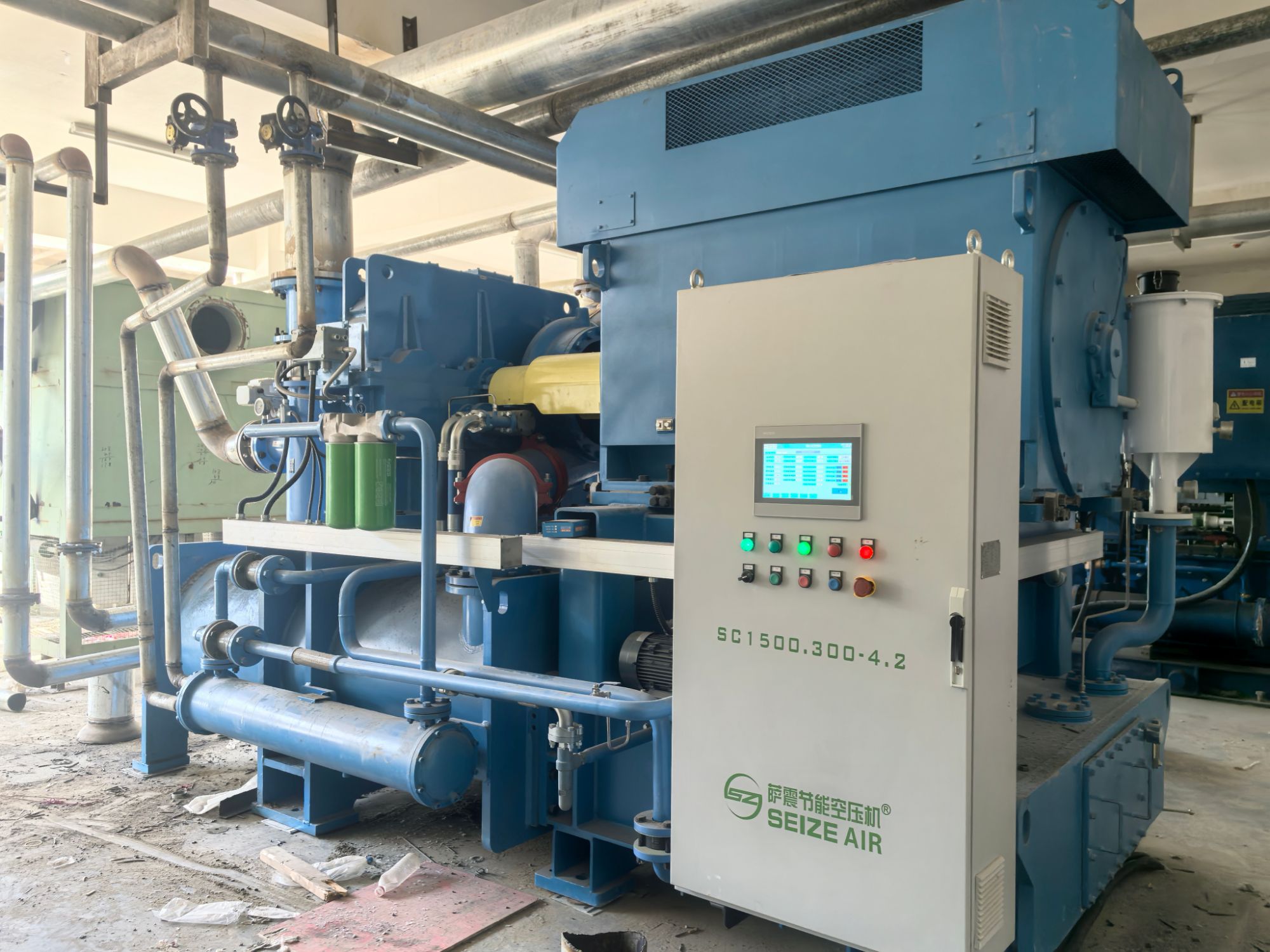
Impeller machining has always demanded an uncomfortable blend of precision and repetition. A single miscount in tool offsets or a moment of distraction during a five-axis blend can scrap a part that has already consumed dozens of hours. Automated cells replace those fragile manual touchpoints with closed-loop control: robots load raw forgings, in-process probes verify each blade and hub before the next cut, and tool wear compensation adjusts on the fly. The result is not just fewer mistakes, but a process that stays within tolerance on the 40th impeller of the week as easily as the first.
What used to sit in a machinist's notebook — the feel for a particular cutter, the subtle shift in fixture pressure — now lives in the cell controller. Error-proofing happens before metal is removed, not after. The system cross-checks part orientation, coolant flow, and spindle load against a digital twin of the intended toolpath. If a deviation exceeds a few microns, the cell pauses and recovers without an operator chasing alarms. That shift removes the biggest variable in impeller production: the assumption that everyone reads a drawing the same way.
For shops that run low-volume, high-mix impeller work, automation is often dismissed as too rigid. But modern cells handle the variation that used to demand human judgment. Pallet changers hold rough and finish ops side by side. Probing routines map each casting's actual geometry before machining, so a slightly shifted core or extra stock doesn't turn into a collision or a scrapped hub. By removing the repetitive decisions that lead to drift and fatigue, these cells let machinists focus on the exceptions rather than guarding against their own errors.
Material Upgrades That Push Compressor Stages Further
Nickel superalloys have long dominated the hot sections of compressors, but their creep resistance falters as stage exit temperatures climb. Shifting to single-crystal blades and powder metallurgy disks buys a modest margin, yet the real step change comes from ceramic matrix composites in stator vanes and shrouds. These materials cut cooling air demand by nearly half while allowing burner discharge temperatures to rise, directly enabling higher pressure ratios per stage without sacrificing part life.
Additive manufacturing opens a different path: internal cooling passages shaped like branching vascular networks rather than straight drilled holes, which drops metal temperatures unevenly and reduces thermal stress. Pairing this with gradient transition joints between dissimilar alloys eliminates the classic failure point at the weld line. On top of that, multilayer environmental barrier coatings protect against oxidation and steam attack, keeping surface roughness low so blade tip clearances stay tight even after thousands of hours.
The practical payoff shows up in stage count. A compressor that once needed fourteen stages to reach a given pressure ratio now manages it in eleven, trimming rotor length, bearing span, and casing weight. For aero engines, that translates into lower specific fuel consumption on long-haul routes; for industrial gas turbines, fewer stages mean shorter maintenance windows and less exposure to fouling in the rear rows. None of this works in isolation—the material choices only pay off when matched with revised aerodynamics and clearance control, but the material upgrade is what makes the tighter design possible in the first place.
In-Process Inspection: Stopping Defects Before They Leave the Line
At Station 7, the torque gun feeds a live reading to the screen above the line. When the number dips to 13.8 instead of 14.5, the operator stops the cycle, checks the air pressure, and resets the clutch. Ten minutes later, the same drift appears again. Instead of letting those fasteners continue down the conveyor, the line pauses and a maintenance tech opens the tool. That's the core of in-process inspection: not waiting for a batch audit at the end of the shift, but catching the small drift while the part is still in front of you.
This approach works best when you pick two or three places where failures actually begin—thread forming, seal insertion, final torque—and equip them with simple checks that fit the operator's rhythm. It might be a go/no-go gauge hanging next to the fixture, a camera that flags missing O-rings, or a digital caliper that logs every fifth measurement. The key is that the check happens in the work sequence, not as a separate audit step. When the result falls outside the band, the operator has the authority to stop and correct, and the data gets tagged with the exact time and station.
Over a few weeks, those tagged measurements reveal patterns. One line might show a slow drop in clamp force after lunch, pointing to tool heating. Another might catch a supplier's batch with slightly thicker gaskets before they reach final assembly. Instead of reworking or scrapping at the end, you're fixing the cause while the defect is still isolated. That keeps bad parts from leaving the line, and it turns the inspection data into a running history of the process rather than just a pass/fail log.
Torque-Controlled Assembly for Leak-Free Housings
Achieving leak-free housings depends heavily on controlling the clamp load across sealing interfaces. When bolts are tightened without torque monitoring, the gasket or O-ring can be crushed unevenly, leaving low-pressure zones where fluid or gas eventually escapes. A defined torque sequence, applied with calibrated tools, distributes compression so that the seal sits evenly against both mating surfaces. This prevents the common failure mode where one corner of a housing lifts just enough to create a micro-leak that only appears under thermal cycling.
In practice, the assembly process uses torque-angle monitoring rather than peak torque alone. As the fastener reaches a threshold, the rotation angle is tracked to confirm that the joint is drawing together smoothly and the gasket is being compressed into its optimal working range—not fully compressed, but held at a predictable preload. Paired with a short pressure decay test after assembly, this approach catches housings that would otherwise pass a visual inspection but fail later due to uneven bolt tension or a pinched seal.
One overlooked aspect is how torque values shift over the life of the housing. Polymers and soft metal flanges creep under sustained load, so the initial torque may relax by 10–20% within the first hundred hours. A robust leak-free design accounts for this by specifying a torque that is high enough to retain sealing force after relaxation, but not so high that it deforms the flange or extrudes the seal. Recording torque data per unit also helps trace any field leaks back to a specific station or tool, closing the loop between assembly parameters and long-term performance.
Digital Twins That Trim Commissioning Time
Commissioning a new production line often means weeks of stop-start testing, waiting for physical equipment to arrive or for technicians to schedule time. A digital twin flips that sequence: the control logic, sensor mapping, and safety interlocks are validated against a virtual replica long before the physical system is powered up. This catches wiring errors and parameter mismatches while they're still cheap to fix.
On site, the same model serves as a live reference. Engineers can run through startup sequences, adjust PID loops, and simulate fault scenarios without disrupting the actual hardware. The result is a commissioning phase measured in days rather than months—and fewer surprises during the first production run. That time savings comes not from rushing the work, but from doing the failure-prone steps in a controlled, virtual environment.
FAQ
It builds machines that push large volumes of gas through pipelines, refineries, and chemical plants. The work includes machining impellers, assembling rotors, and running them on test stands to prove they meet performance specs.
Instead of relying on manual fitting and lengthy trial runs, the factory uses five-axis machining, laser alignment, and automated inspection. Tolerances get tighter, and each part is checked against its digital twin before it ever goes into an assembly.
These rotors can spin above 20,000 rpm. Even a few grams of imbalance at that speed creates destructive vibration. High-speed balancing rigs measure and correct the rotor in multiple planes, so the machine runs quietly for years.
Before cutting steel, engineers run computational fluid dynamics and finite element analysis on the impeller and casing. That lets them spot choke points or stress risers on screen, not on a $50,000 casting.
Yes, and it shows in the details. Test rigs recover heat, machine tools use regenerative drives, and coolant is filtered and reused. The factory's own power bill drops while it builds equipment that saves energy for the customer.
Every component gets a digital record of its machining, heat treatment, and inspection results. If a bearing runs hot in the field five years later, the factory can pull that record and find the exact batch or operation that needs attention.
It depends on the order, but most units get a mechanical run test and a performance test against the contract curve. Large or critical machines may also run a full string test with the driver and coupling to verify the entire train.
Workers now spend more time programming CNCs, reading sensor dashboards, and managing robotic cells than doing hand grinding. It's more about interpreting data and catching anomalies early than about physical strength.
Conclusion
Precision balancing, automated impeller machining, and upgraded materials now work together inside the centrifugal compressor factory to lift industrial efficiency well beyond older build methods. Rotors are balanced under full-load conditions using real-time vibration feedback instead of manual trial-and-error, so they stay stable at operating speeds that would have caused walk-off or fatigue failures a decade ago. Automated cells machine impellers with micron-level repeatability, removing hand-finishing variability and ensuring every vane profile matches the design intent. Material upgrades—including higher-strength alloys and advanced coatings—allow each compressor stage to run at higher pressure ratios and temperatures without enlarging the casing or adding extra stages. In-process inspection closes the loop by measuring critical features immediately after machining; any drift is corrected at the station, not discovered later on a test stand.
Assembly also benefits from torque-controlled fastening that clamps housings evenly, preventing leak paths that would sap efficiency or force rework after shipment. Meanwhile, digital twins cut commissioning time by validating control logic and surge margins against a virtual machine before the physical unit is ever started on site. These are not isolated upgrades—they feed into the same goal: tighter tolerances, faster ramp-up, and fewer warranty claims. By combining metrology, automation, and virtual simulation on the factory floor, the plant turns advanced manufacturing into a direct driver of industrial efficiency, delivering compressors that reach full output sooner and hold it longer.
Contact Us
Contact Person: Mia
Email: [email protected]
Tel/WhatsApp: +86 19821985894
Website: https://www.seize-air.com